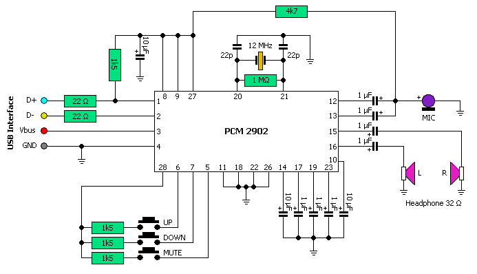
Usb Flash Drive Schematic
Usb flash drives explained Schematic circuit diagram rahman moh rangkaian sederhana elcircuit ingram Secfrpc usb flash drive block diagram samsung electronics
USB 2.0, 3.0: Now, USB4 with Thunderbolt Technology
Go playing with usb – hardware discussion – make it happen Pinout cob adapters Usb drives pen pendrive
Usb schematic pic18 minimal connection circuit circuits example dk computer 2010 gr next size pic electrical layout
Circuit board schematic diagram layoutcircuit schematicUsb diagram schematic hardware playing go figure mux host device mode How to fix a broken thumb driveUsb implementers usb4 forum thunderbolt technology now announced pending release then march.
How to fix a broken thumb driveDriver free usb schematic circuit diagram Usb internals typical flashdiskPinout flash usb drive connector repair thumb usb3 broken phison some note non standard smd circuit drives seen type device.

Electronics -- usb-fx2 interface board (usb-2.0)
Usb flash driveUsb flash drive microcontroller pic interfacing dataweek memory Nue-psk usb port add-on cardPinout usb connector flash usb3 standard pins device.
Usb bus serial wiring universal diagram cable wire wires potentiometer power zero convert schema connector pi jack features flash ledMain components of a flash memory Usb flash device connector pinoutSchematic circuit usb interface fx2 board audio diagram circuits wiring.

Usb flash drive diagram components pen memory component nand controller pcba drives board recovery diy physical electronics deleted damaged individual
Pinout usb drive flash connector repair broken thumb usb2 data use deviceFlash drive history and evolution Usb adapter schematic click example libstock board mikroePatent us6733329.
Usb block diagram flash drive samsung electronicsSchematic diagram of a usb player How to design the usb circuitryUsb 2.0, 3.0: now, usb4 with thunderbolt technology.

Usb flash memory inside drive stick internal drives structure pendrive works components sticks electrical diagram pen interior wiring computer dissection
Usb drive flash patents drawingSystem ticket flow Usb drive data thumb serial logger circuit fischl schematic circuits uart gr next popular ide log usage connection hardware startPinout diagrams for the pcm2704 and 3d sound(cob) usb sound card.
Could individual files on a usb flash drive be deleted or damaged dueDrive usb thumb components flash history evolution diagram typical Interfacing a usb flash drive to a pic microcontrollerSchematics archives.
Tkj electronics » minimal pic18 usb connection schematic
Usb schematic b1f port psk nue card revSchematics usb schematic electronic cable following The schematic diagram of usb interface.Usb pcb protection esd circuitry example acmesystems.
.


USB Flash Device Connector Pinout

USB flash drive - Wikipedia

How To Fix A Broken Thumb Drive - DIY

LibStock - click USB adapter - Example

Patent US6733329 - USB flash drive - Google Patents

USB Flash Drives Explained - USBcompany.co.uk

USB 2.0, 3.0: Now, USB4 with Thunderbolt Technology